
Using Joysticks and Arduino Analog Pins to Control Robot Servo Motors
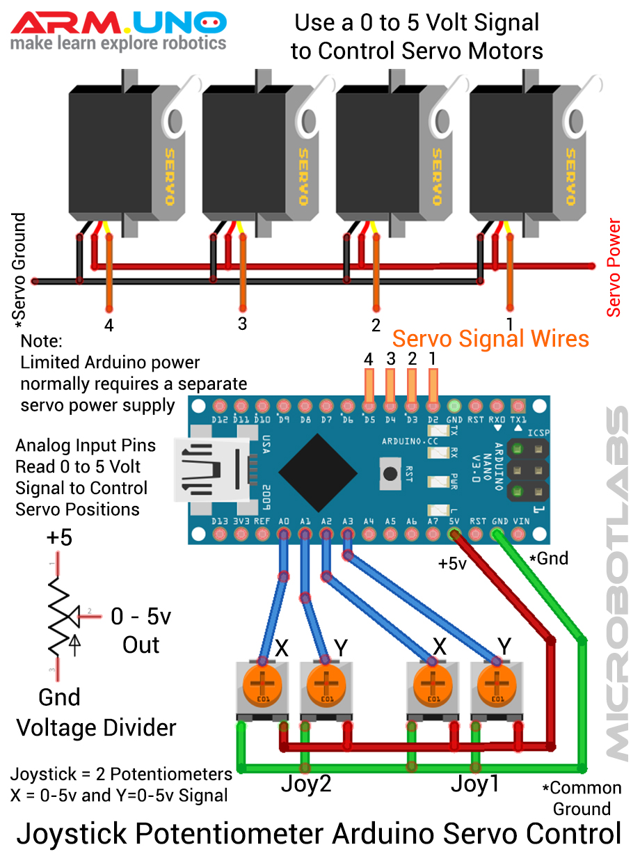
Joysticks combine two variable resistors called potentiometers. We can use the Arduino's analog input pins to read each potentiometers position and then use this information to control the rotational position of a servo motor. The Arduino's analog input pins measure voltage values of 0 to 5 volts. We can connect the joysticks potentiometers to create a circuit called a voltage divider. Connecting ground (0 volts) to one side and +5 volts to the other side will allow the potentiometers center wiper pin to output a voltage of 0 to 5 volts depending on the joysticks knob position.
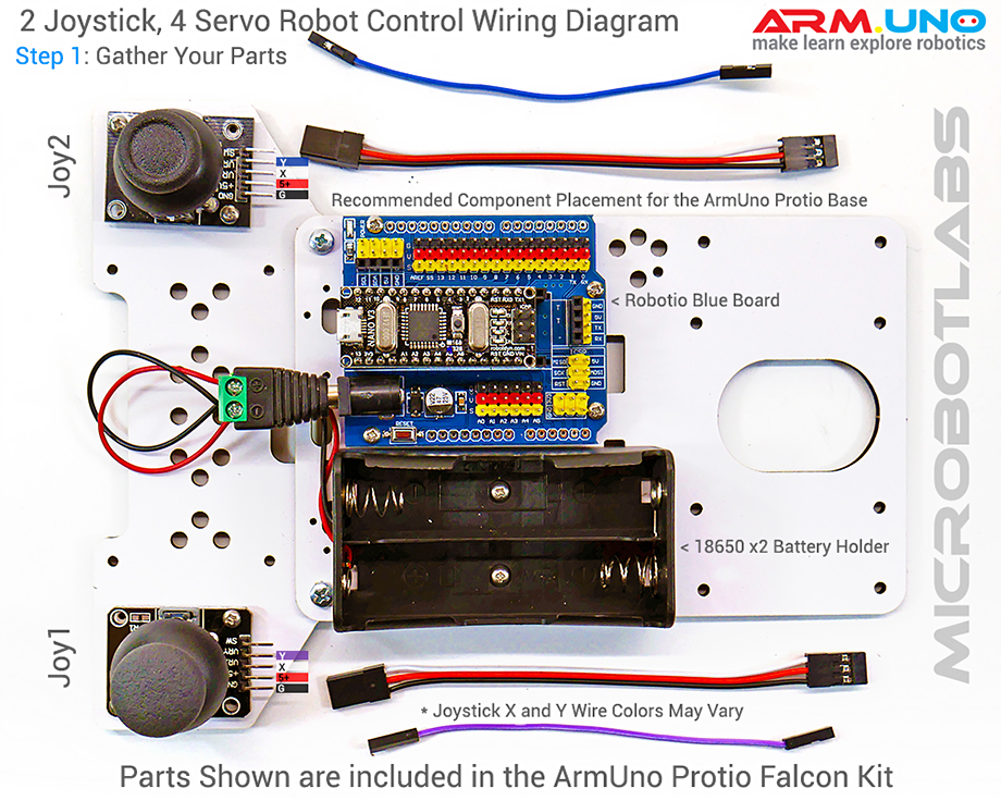
First lets wire up two joysticks (total of four potentiometers) to our micro-controller. The images below use a Robotio control board and the included wires and cables that are part of the Armuno Protio Falcon Robotic Arm kit. You can substitute a generic Arduino Uno or Nano with your Armio, MeArm or similar robot and your own wires to get the same result.
The Arduino source sketch code needed to read the joysticks sensors and control the servo motors is listed near the bottom of this page.
Joystick Potentiometer Arduino Servo Control Generic Diagram
Controlling Your ArmUno Robotic Arm with Joysticks
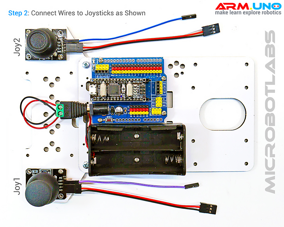
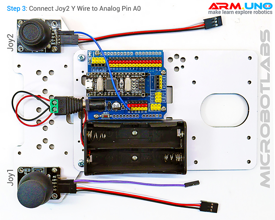
Follow the illustrated steps below to set up your robot arm to allow control with a couple of joysticks. we use the Armuno Base, Protio Joypad and the Robotio Nano Controller Board in this example but you can substitute generic parts and get the same result.
Step 2: Connect wires and cables to the joystick modules.
Step 3: Connect joystick-2 Y pin to analog pin A0.
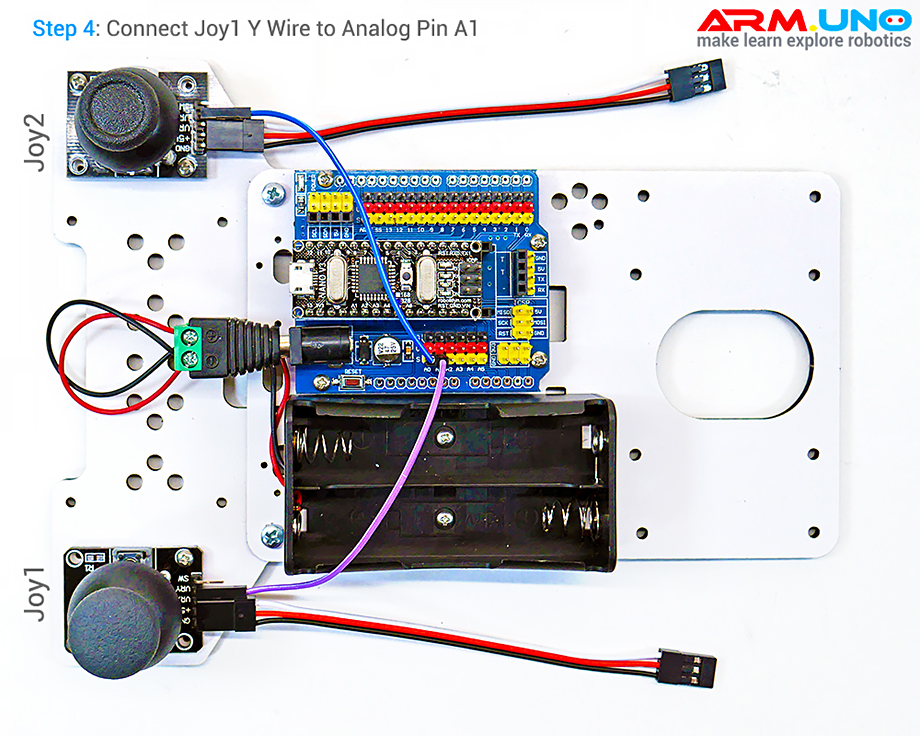
Step 4: Connect joystick-1 Y pin to analog pin A1.
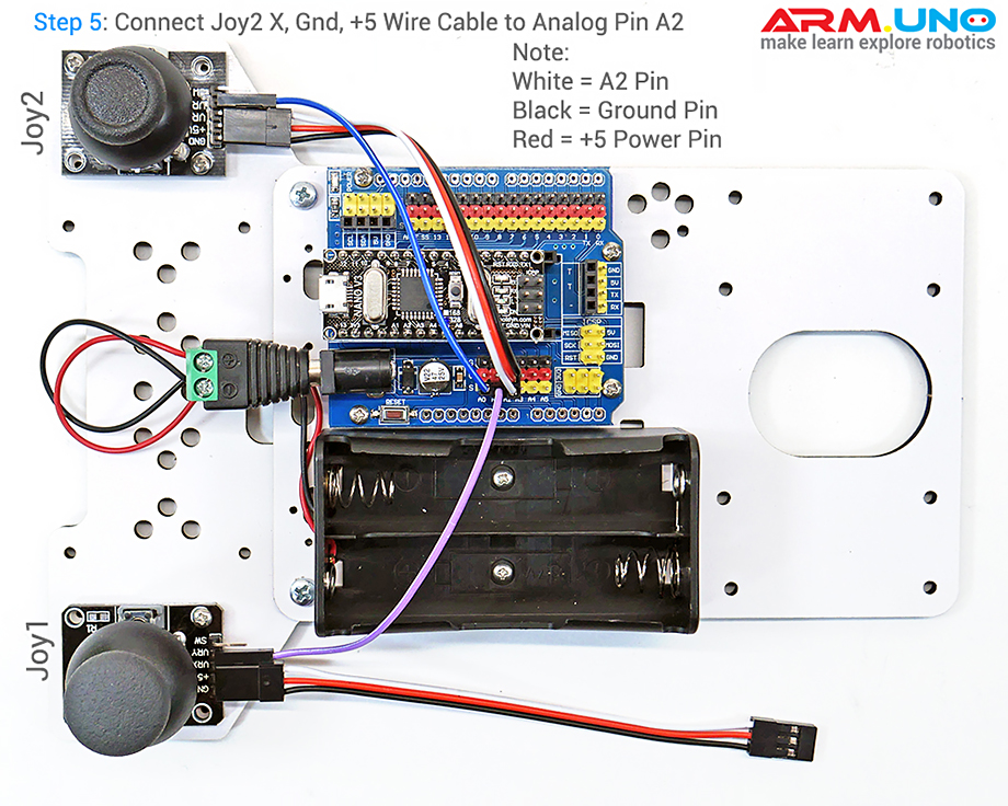
Step 5: Connect joystick-2 X, Gnd and +5v pins to analog pin A2.
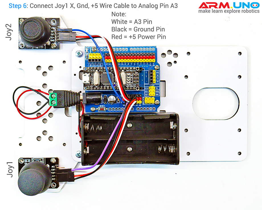
Step 6: Connect joystick-1 X, Gnd and +5v pins to analog pin A3.
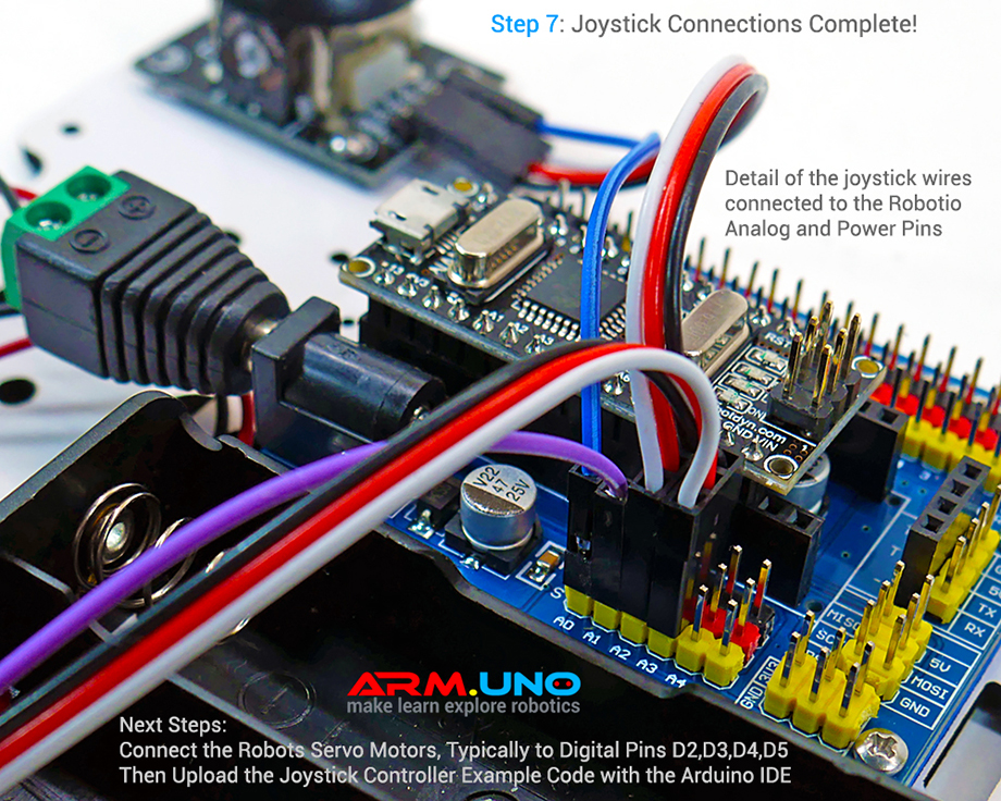
Step 7: Your joystick connections are complete!
Joystick servo control Arduino sketch source code.
Read code comments and make adjustments for your setup. Copy and Paste code into Arduino IDE software to upload to your device.

Copyright © MICROBOTLABS
Our Make & Learn Brands: MICROBOTLABS™ ARM.UNO™ ROBOTIO™ PROTIO™ ARMIO™ ANITRON™ ANITRONIC™ ARM.ONE™

